EN
EN

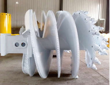
The 40% Efficiency Drop – A Soil Mismatch Case Study
A foundation contractor in Texas was drilling 60 piles for a new bridge project. They had a standard continuous flight auger set up for clay—which worked well for the first 40 piles. Then the ground changed. What was documented as stiff clay turned out to be weathered limestone with intermittent gravel lenses. The auger teeth—standard soil teeth—were wearing out every 15 meters. Penetration rate dropped from 45 minutes per pile to over 75 minutes. The project fell two weeks behind schedule, and the contractor spent $12,000 on emergency tooth replacements and overtime.
The problem? The auger design—flight pitch, tooth type, and torque settings—was never adjusted when the soil profile changed. A site superintendent with the right soil analysis could have switched to a rock auger with carbide teeth before the problem developed. Instead, the crew kept drilling with the wrong tool until failure forced a change.
This scenario is more common than most foundation contractors admit. Over the past seven years, our drilling tools team has investigated over 150 pile foundation projects where auger selection was a contributing factor to delays, cost overruns, or quality issues. The consistent finding is that mismatched auger specifications account for nearly 30% of pile foundation delays—often due to oversized bits causing borehole collapse or undersized tools requiring multiple passes. Understanding how to match drilling auger design to soil conditions isn't just about equipment selection; it is about protecting your schedule, your budget, and your reputation.
Soil Condition Matching – From Soft Clay to Weathered Rock
Selecting the correct drilling auger starts with a thorough analysis of on-site soil conditions. Soil type directly influences flight design, tooth choice, and torque requirements. A mismatch often causes slow penetration, premature wear, or borehole instability.
| Soil Type | Recommended Auger Type | Flight Pitch | Typical Diameter Range |
|---|---|---|---|
| Soft clay / loose silt | Continuous flight (shallow helix) | Low angle | 4–8 inches |
| Dense clay / compacted loam | Continuous flight (steeper angle) | Moderate | 8–18 inches |
| Loose sand | Wide‑flight auger | Steep | 8–24 inches |
| Weathered rock | Heavy‑duty rock auger | Variable | 12–36 inches |
| Hard bedrock | Rock auger with carbide teeth | Variable | 12–36 inches |
Soft, Cohesive Soils
Soft, cohesive soils like clay and loose silts perform best with continuous flight augers featuring a shallow helix pitch—this geometry slices efficiently while minimizing clogging. Dense clay and compacted loam require moderate torque and a steeper flight angle to shear without over-compacting the formation.
In loose sand, wide-flighted augers move spoil outward to stabilise the borehole wall. Field testing confirms that selecting an auger based solely on diameter—without soil analysis—can reduce drilling efficiency by up to 40%.

Weathered Rock and Hard Bedrock
In weathered rock or hard bedrock, robust rock augers with heavy-duty flights and specialised teeth are essential. Industry data shows auger diameters for soft soils typically range from 4 to 8 inches, whereas hard-rock applications demand 12- to 36-inch augers backed by high hydraulic power. For mixed-ground profiles, quick-change systems allow rapid adaptation without extended downtime.
Soil Teeth vs. Rock Teeth – Performance and Wear Life
Soil teeth are cast-steel components with sharp cutting edges optimised for loose or cohesive ground; they slice cleanly but wear rapidly in abrasive rock. Rock teeth integrate tungsten carbide inserts brazed onto heavy-duty bodies, enabling grinding action through hard formations.
| Feature | Soil Teeth | Rock Teeth |
|---|---|---|
| Material | Cast steel | Tungsten carbide inserts on steel body |
| Best application | UCS < 10 MPa | UCS 25 MPa |
| Wear life (granite) | 20–30 meters | 100+ meters |
| Cost per tooth | Lower | Higher |
| Heat generation | Low | High (requires flushing) |
| Transitional ground | Limited | Bullet-style offers compromise |
Independent wear tests show rock teeth outlast soil teeth by a factor of 3 to 5 in granite or basalt—sustaining effective cutting over 100+ meters versus just 20–30 meters for standard soil teeth. However, rock teeth generate more heat and require adequate flushing to prevent insert loss. Soil teeth perform efficiently in formations with unconfined compressive strength (UCS) below 10 MPa; rock teeth become necessary above 25 MPa. For transitional ground, bullet-style teeth offer a balanced compromise. Proactive monitoring and timely replacement—before critical wear occurs—help avoid costly downtime and preserve pile quality.
CFA vs. Hollow Stem Auger – Choosing the Right Method
For cast-in-place piles, the choice between continuous flight auger (CFA) and hollow stem auger significantly affects torque demand, spoil handling, and grout placement quality.
| Feature | CFA Auger | Hollow Stem Auger |
|---|---|---|
| Spoil transport | Through flights (external) | Through central tube (internal) |
| Torque requirement | Higher (flight friction) | ~30% lower (cut-and-core) |
| Borehole stability | Excellent; soil plug stabilises | Risk of collapse in loose ground |
| Grout placement | Pressurised through hollow stem | After core removal (risk of voids) |
| Best application | Unstable/variable strata | Soft, cohesive soils |
| Spoil containment | Requires collar management | Clean; centralised extraction |
CFA – Continuous Flight Auger
CFA drilling uses the auger's flights to transport spoil upward, forming a stabilising soil plug within the bore. Torque is driven by soil shear resistance and auger diameter—for example, approximately 150 kNm is typical for a 900 mm auger in dense sands. Spoil emerges continuously at the collar, requiring coordinated removal. At target depth, concrete or grout is pumped under pressure through the hollow stem as the auger withdraws, expelling water and debris to form a continuous, high-integrity shaft—provided withdrawal rate precisely matches grout flow.
CFA excels where borehole stability and pressurised grouting are critical—especially in unstable or variable strata.
Hollow Stem Auger
Hollow stem augers extract soil through a central tube, eliminating flight-based spoil friction. This cut-and-core method reduces torque by roughly 30% compared to CFA in cohesive soils. Spoil exits cleanly through the inner tube, simplifying containment. Grout is then pumped down the hollow stem after core removal—but the unsupported borehole risks collapse in loose or saturated ground, potentially compromising grout continuity and pile integrity.
Hollow stem augers suit soft, cohesive soils where lower torque and centralised spoil control are priorities. Strict adherence to controlled grouting procedures is essential to maintain pile quality.
Aligning Auger Specifications with Project and Equipment Constraints
| Parameter | Consideration | Impact |
|---|---|---|
| Pile depth | <6 ft: standard flight; >6 ft: extension auger | Determines auger length and joints |
| Pile diameter | 12–24 in typical; larger increases torque demand | Influences flight width and hub strength |
| Flight pitch | Steeper = faster spoil transport | Tuned to soil type |
| Kelly bar compatibility | Torque rating vs. rig hydraulic output | Prevents strain or inefficiency |
Project depth, required pile diameter, and load-bearing demands directly dictate auger geometry, flight pitch, and compatibility with the drill rig's Kelly bar. Industry analysis links mismatched auger specifications to nearly 30% of pile foundation delays—often due to oversized bits causing borehole collapse or undersized tools necessitating multiple passes.
For depths under 6 ft, standard flight augers (12–24 in diameter) usually suffice. Beyond that, extension augers with carbide-tipped cutting edges improve spoil evacuation and structural durability. Larger diameters increase torque demands and require wider flights and reinforced hubs to handle higher load-bearing stresses.
Flight pitch—the helix angle—must also be tuned: steeper pitches accelerate spoil transport, crucial in deep or cohesive soils; shallower pitches support controlled, low-disturbance cutting in granular materials.
Equally important is Kelly bar compatibility: the auger's torque rating and rotational speed must align with the rig's hydraulic output to prevent strain or inefficiency. Adapters may bridge minor mismatches but must be applied strictly per manufacturer guidance to ensure safety and performance.
Optimising Installation Parameters – Achieving Quality Pile Execution
Achieving consistent pile integrity begins at excavation—not concrete placement—and hinges on precise control of installation parameters. Rotational speed, crowd force, and penetration rate must be continuously adjusted in response to real-time soil feedback.
| Parameter | Recommended Practice | Warning Sign |
|---|---|---|
| Rotational speed | Adjust to soil density | Over‑rotation in loose sand causes collapse |
| Crowd force | Maintain steady penetration | Insufficient force slows progress; overheats tool |
| Penetration rate | Controlled; avoid over‑flighting | Aggressive pulling creates voids |
| Vertical alignment | Check with inclinometer; ≤1:100 tolerance | Deviation 1–2% causes eccentric loading |
The objective is steady, controlled advance—neither over-excavating nor excessively disturbing surrounding ground. Excessive rotation in loose sands can trigger borehole collapse; insufficient crowd pressure in dense clays slows progress and overheats the tool.
Hydraulic pressure and torque readings provide immediate indicators: a sudden spike often signals a stratum transition, warranting reduced penetration rate and possibly slower rotation to protect the cutting structure. Operators should also avoid "over-flighting"—aggressively pulling cuttings—which can create voids and weaken later grout encapsulation.
Vertical alignment is equally critical. Deviations of just 1–2% over deep piles cause eccentric loading and reduce structural capacity. Using a spotter or digital inclinometer to verify plumb at regular intervals—and adjusting mast tilt during drilling—ensures compliance with common tolerances (e.g., 1:100). Finally, auger extraction during spoil removal must be carefully regulated; retracting too quickly creates suction that destabilises the borehole wall.
Quality Assurance – What to Look for in an Auger Supplier
| Evaluation Criterion | What to Verify | Why It Matters |
|---|---|---|
| Carbide grade | Wear resistance; impact toughness | Determines wear life in hard ground |
| Flight weld quality | Full penetration; no defects | Prevents flight separation under load |
| Kelly bar compatibility | Torque rating; shank interface | Ensures safe, efficient operation |
| Field performance data | Independent test results | Validates performance claims |
| Maintenance support | Parts availability; service network | Minimises downtime |
Engineering Partnership – What G-Honor Games Brings to the Table
Achieving consistent, efficient drilling performance across varying soil conditions requires more than selecting an auger from a catalogue—it demands a manufacturing partner that understands soil mechanics, auger geometry, and field reliability. G-Honor Games brings this integrated approach to drilling auger manufacturing. Our augers are engineered with flight designs matched to specific soil types—from shallow-pitch continuous flights for clays to heavy-duty rock augers with carbide-tipped teeth for hard bedrock. Our welding procedures follow AWS D1.1 standards with full-penetration groove designs and documented quality control for every unit. Our engineering team collaborates directly with foundation contractors to match auger diameter, flight pitch, and tooth configuration to project-specific soil reports and rig specifications. For drilling contractors and foundation engineers, this translates to faster penetration, consistent borehole quality, and lower cost per pile.
FAQ
Q: What factors should I consider when choosing a drilling auger?
A: Key factors include soil type (UCS, abrasiveness), project depth, required pile diameter, and drill rig hydraulic output. A mismatch can reduce efficiency by up to 40%.
Q: What is the difference between soil teeth and rock teeth?
A: Soil teeth are cast steel for loose or cohesive ground (UCS <10 MPa). Rock teeth have tungsten carbide inserts for abrasive rock (UCS >25 MPa) and last 3–5 times longer in granite.
Q: When should I choose CFA over a hollow stem auger?
A: CFA is preferred in unstable or variable strata where borehole stability and pressurised grouting are critical. Hollow stem augers suit soft, cohesive soils where lower torque and clean spoil extraction are priorities.
Q: How does flight pitch affect drilling performance?
A: Steeper pitches accelerate spoil transport—important in deep or cohesive soils. Shallower pitches provide controlled, low-disturbance cutting in granular materials.
Q: What is the importance of Kelly bar compatibility?
A: The auger's torque rating and rotational speed must align with the rig's hydraulic output. Mismatches cause strain, inefficiency, or safety risks—adapters should only be used per manufacturer guidance.
Q: What tolerance should I maintain for vertical alignment?
A: Typical tolerance is 1:100 (1% deviation). Exceeding 1–2% over depth causes eccentric loading and reduces pile structural capacity.